![]() Modern electronic devices are made of certain fundamental building blocks, for example capacitors. Understanding their properties is with respect to their geometrical parameters is of great importance particularly in electrical engineering. In this problem we will calculate the features of a coaxial capacitor that contains two different media.
Modern electronic devices are made of certain fundamental building blocks, for example capacitors. Understanding their properties is with respect to their geometrical parameters is of great importance particularly in electrical engineering. In this problem we will calculate the features of a coaxial capacitor that contains two different media.

Problem Statement
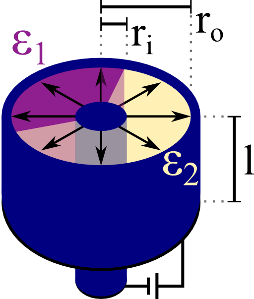
A cylindrical (or coaxial) capacitor is made of two concentric metallic cylinders. Let the radius of the inner cylinder be ri and ro for the outer one. In-between the cylinders are two media with different relative permittivities ε1 and ε2.
The two boundaries between these media may also be radial, see schematic on the right. Each medium has a certain filling fraction α1 and α2, respectively.
Calculate the capacitance C per length l for this device with respect to the given parameters.
Background
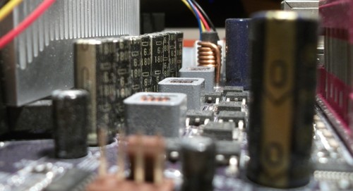
Microelectronics is a truly fascinating field. Let's take a close look at some motherboard which is the central part of a computer - the processor, graphics card etc. are connected to it:

On the left we can see the cooler of the processor. Close to it there is a line of labeled pillars - electrolytic capacitors. These components are one of the main building blocks of electronic devices.
Their inner structure is a little bit more complicated than that idealized coaxial capacitor we want to understand in the given problem. We will however be able to deduce some physical properties.
Hints
What is the capacitance of a cylindrical capacitor with just one dielectric inside? How can we use this result to calculate the capacitance of the given device using the filling fractions αi?
Solution
This problem can be solved fastly if we remember the boundary conditions of the electric field \(\mathbf{E}\) and the electric displacement field \(\mathbf{D}\). At the boundaries between the two media, the tangential part of the electric field has to be continuous which is in our case the \(\rho\) component\[E_{\rho}^{1}=E_{\rho}^{2}\ .\]
This implies that the electric field everywhere inside the capacitor has the same form and is only depending on the radial coordinate \(\rho\). This does not hold for \(\mathbf{D}\) which will be different inside the different media since \(\mathbf{D}=\varepsilon\mathbf{E}\). In turn, the charges at the metal-dielectric boundaries will have different surface charges for both domains.
However, these surface charges will be independent of each other since the electric field is the same in both domains. So we can deduce that the capacitance of the configuration will be the sum of the capacitances of each part of the cylindrical capacitor. That means that we only have to calculate the capacitance of such a capacitor with just one medium and add these capacities up - with respect to the filling fractions \(\alpha_{i}\):\[C=\alpha_{1}C_{1}+\alpha_{2}C_{2}\ .\]
So, what is the capacitance of a homogeneously filled coaxial capacitor? From our calculations for a line charge we know already that the potential of an infinitely long line charge. Given a line charge density \(\eta=Q/l\) in some medium with permittivity \(\varepsilon=\varepsilon_{0}\varepsilon_{r}\), this potential reads as \[\phi_{\mathrm{linecharge}}\left(\mathbf{r}\right) = -\frac{\eta}{2\pi\varepsilon_{0}\varepsilon_{r}}\log\left[\rho\right]\ ,\] up to an arbitrary constant. Now, the capacitance is the charge that a device can store given a certain potential difference \(V=\Delta\phi\), \[C = \frac{Q}{V}\ .\]
Now we don't want to go into too much detail about capacity coefficients and use the absolute value of the potential difference to not get confused with sign changes. We compute the capacitance per length as\[\begin{eqnarray*}\frac{C}{l} &=&\frac{Q}{l\left|V\right|}=\frac{2\pi\varepsilon_{0}\varepsilon_{r}}{\left|-\log\left(r_{o}\right)+\log\left(r_{i}\right)\right|}\frac{Q}{\eta l}\\ &=& \frac{2\pi\varepsilon_{0}\varepsilon_{r}}{\log\left[r_{o}/r_{i}\right]}\end{eqnarray*}\] naturally assuming \(r_{0}>r_{i}\). We can see the similarities to the capacitance of a parallel plate capacitor with capacitance \[C_{\mathrm{plates}} = \varepsilon_{0}\varepsilon_{r}\frac{\mathrm{area}}{\mathrm{distance}}\ .\]
In our case, the area is replaced by the length \(l\) of the capacitor and the distance by the logarithm of the ratios of outer and inner radius. This means that the capacitance in both cases increases dramatically if the distance between conducting layers goes to zero.
In reality, however, there are limits since also the electric field between the plates or cylinders will grow rapidly. Then, the embedded dielectric might not be able to resist the strong forces - they exceed the so-called dielectric strength. So, the usual engineering trick is to use a much larger area. In simple terms, electrolytic condensators can be produced rolling up a somehow layered plate capacitor. Only then, the high capacitances and low volumes needed for modern electronics can be reached.
But let's return to our specific design of the coaxial capacitor with two embedded media. Using the filling fractions \(\alpha_{i}\) we finally find\[\begin{eqnarray*} \frac{C}{l} &=& \alpha_{1}\frac{C_{1}}{l}+\alpha_{2}\frac{C_{2}}{l}\\&=&\frac{2\pi\varepsilon_{0}}{\log\left[r_{o}/r_{i}\right]}\left\{ \alpha_{1}\varepsilon_{1}+\alpha_{2}\varepsilon_{2}\right\} \ .\end{eqnarray*}\]
It is remarkable how little effort we had to put into actual calculations once we knew that this capacitor can be seen as a parallel arrangement of single coaxial capacitors weighted by their respective filling fraction.


